Apparatus
for Ultra-cold Matter

   The apparatus for ultra-cold matter studies, including interferometry and condensed matter research, will be constructed on two optics tables. The apparatus will use rubidiumbosonic 87Rb, and potassium, fermionic 40K, for experiments on ultra-cold quantum degenerate gases -- respectively, Bose-Einstein Condensates (BEC) and Degenerate Fermi Gases (DFG) . We use the rubidium to sympathetically cool the fermionic potassium to degeneracy during the final evaporative cooling stage. Two optics tables serve as a foundation for the following equipment and systems:

   Starting with the MOT, the above list also follows the steps involved in a single experimental cycle for producing an ultra-cold degenerate gas, such as a Bose-Einstein Condensate (BEC) or a Fermi Degenerate Gas (DFG) -- typical cycle time is 5-30 seconds.


          Diagram of apparatus.


UHV Vacuum System
   Laser cooling of atoms in a MOT requires a UHV vacuum of 10-9 Torr, while evaporative cooling of atoms in a magnetic trap and many experiments with ultra-cold atoms requires UHV vacuum of 10-10 Torr or better. The vacuum system consists of two sections: MOT chamber and chip science chamber.


MOT Chamber
   The MOT Chamber consists of double ended rectangular glass cell attached to 4.5" CF cube, pumped by an ion pump and a turbo pump (attached to cube with an angle valve, and pumped by a roughing pump). A residual gas analyzer (RGA) is also attached to the cube for UHV vacuum pressure and debugging.

Chip Science Chamber
   This chamber consists of a small rectangular glass cell attached to a 2.75" CF cube, pumped by an ion pump, Non-Evaporable Getter (NEG) pump material. The chip is attached to the bottom of a copper column attached to the cell's top flange. The BECs and DFGs are produced on the chip, and experiments are then conducted with them.

   The two vacuum system are connected by a bellows. A vacuum shutter and a thin tube inside the bellows isolates the vacuums of the two sections.


Vacuum system components.


Magneto-Optical Trap

   The Magneto-Optical Trap (MOT) cools and traps atoms from a room temperature gas to temperatures on the order of 100 mK. The invention of the MOT in 1987 at Bell Labs and optical molasses has revolutionized atomic physics and the field of ultra-cold matter, and was the basis for the 1997 Nobel Prize in Physics. We use the MOT and optical molasses as the first step towards producing a quantum degenerate gas of ultra-cold atoms.


MOT elements
The MOT apparatus, depicted in the figure on the right, consists of the following parts:

  • Glass UHV vacuum cell: a UHV vacuum environment is necessary to minimize collisions with room temperature atoms and molecules.

  • Laser beams: Six laser beams , two counter-propagating along 3 seperate axes provide the cooling force necessary to slow atoms down from the background room temperature gas. The lasers also confine the atoms through a position dependent force, modulated by a quadrupole magnetic field. The optical frequency of the lasers is stabilized to better than a 1 MHz (4 parts per 108). Two sets of overlapping laser beams at 780 nm and 767 nm provide the cooling and trapping light for 87Rb and 40K, respectively.

  • Magnetic quadrupole coils: Two magnetic field coils (blue doughnut pair in figure on right) in anti-Helmholz configuration generate a magnetic quadrupole field gradient. This spatial varying magnetic field controls the strength of the optical trapping force, so that it is zero at the center of the quadrupole field, where the magnetic field is nul -- the cold atoms collect at the magnetic field zero .

  • Dispensers: Commercial dispensers supply a small background gas of rubidium and potassium.


Schematic of MOT apparatus
(with the cold atoms represented by the glowing orange ball,
and one quadrupole coil cut in half for illustrative purposed).

Basic MOT Physics
   The MOT slows down background gas atoms primarily through the mechanism of Doppler cooling. The MOT traps the cold atoms by increasing the strength of the Doppler cooling force as an atom moves away from the magnetic field zero.

Doppler Cooling
   We consider a two-level atom with a ground state and an excited state, as depicted in the figure on the right. We adjust a laser so that its energy, or frequency, is slightly less than the energy of the atomic ground-to-excited transition. The atom will absorb and randomly re-emit photons from the laser beam more frequently as the energy of the laser gets closer to the energy of the ground-to-excited transition.

   If we shine two such counter-propagating laser beams on a moving atom, then in the lab frame we have the following situation:


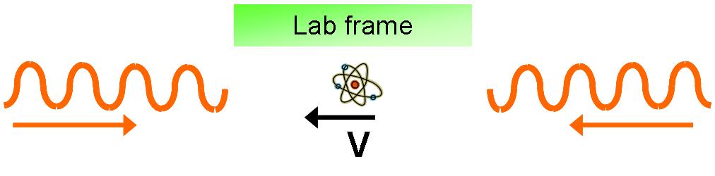
   In the lab frame the difference between the atomic transition energy and the laser energy, or frequency, is d. 
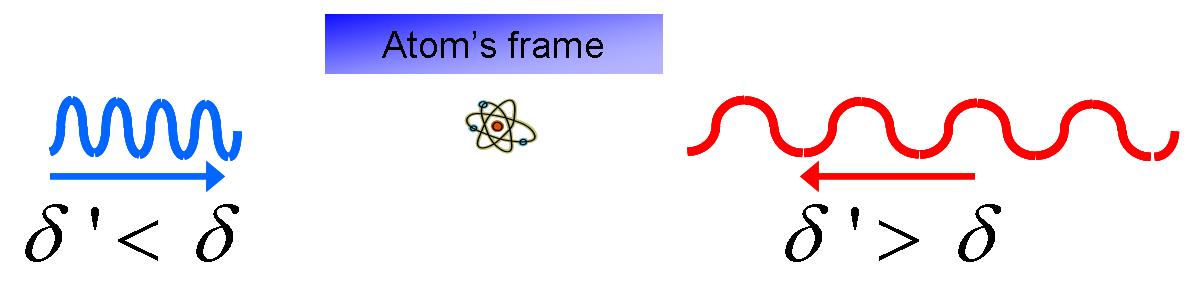
In the frame of the moving atom, the atom sees each of the counter-propagating lasers at a different energy, due to the Doppler effect. The atoms sees the laser beam it is travelling towards with a higher frequency (blue shifted), closer to the ground-to-excited transition, while it sees the laser beam it is travelling away from with a lower frequency (red shifted), further from the ground-to-excited transition.

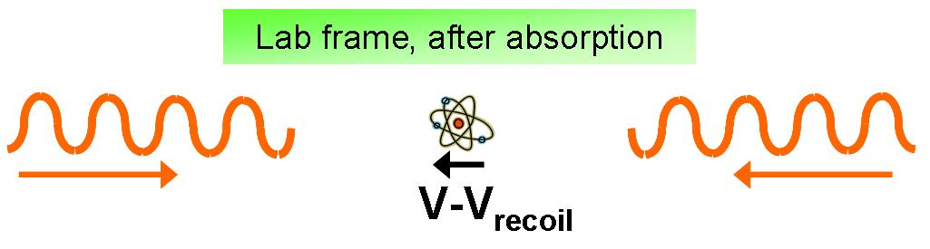
  Consequently, the atom absorbs (and re-emits) more photons from the laser beam it is travelling towards and less from one which it is moving away.
   With each photon absorption and re-emission event, the atom gets a little recoil velocity/momentum kick in the direction of the laser beam from which it absorbed the photon. Since the atom tends to scatter more photons from the beam it is travelling towards, then on average the atom slows.

   While each kick is not very large, just 6 mm/s in the case of 87Rb, this force produces a massive decceleration, since there are typically 107 scattering events per second. The strength of the Doppler force depends on the velocity of the atom, and has the following velocity dependence for 87Rb:


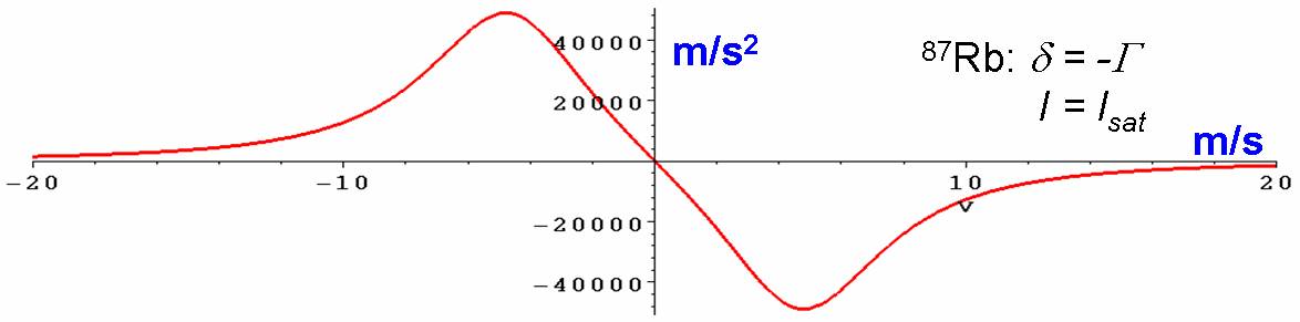
   While the plot shows the force operating down to a zero velocity, Doppler cooling cannot reduce an atom's velocity to zero. The random photon re-emission associated with each absorption process acts to counteract Doppler cooling and limits the final attainable temperature, the Doppler temperature. In the case of 87Rb, this minimum velocity is about 10 cm/s, which corresponds to a temperature of about 180 mK.
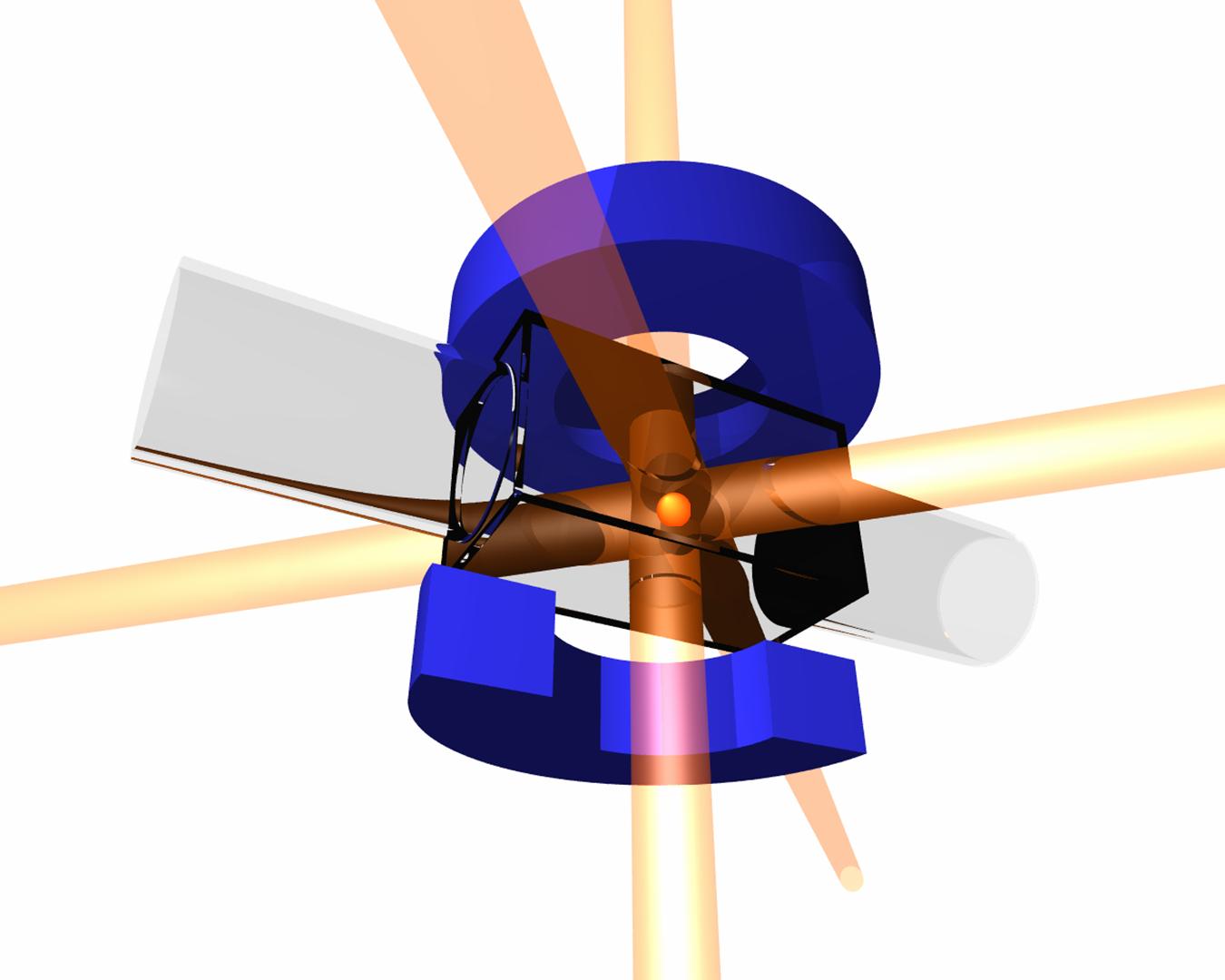
Trapping
    Doppler cooling affects only the velocity of the atoms. Once the atoms have been cooled to the Doppler temperature, they are free to diffuse around at 
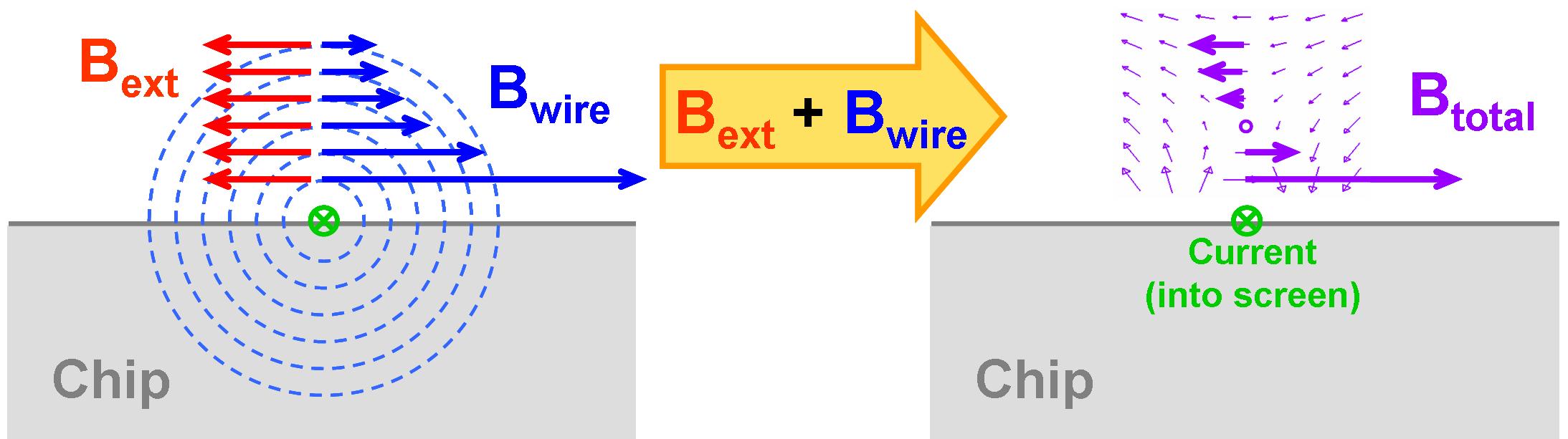
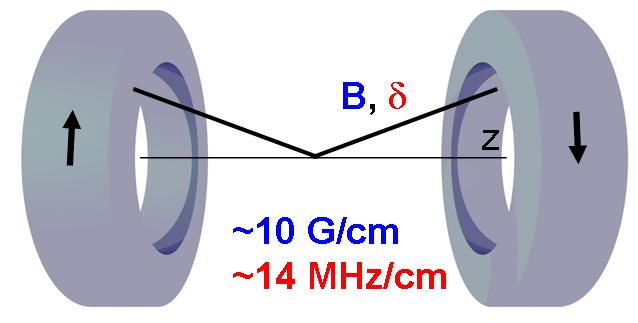
their Doppler velocity. The addition of spatially dependent magnetic field changes the energy of the atom's ground-to-excited transition through the Zeeman effect. If the magnetic field strength increases away from the center of the quadrupole coil pair, then the energy of the atomic ground-to-excited transition will decrease (if the atom is optically pumped into the correct magnetic substate), approaching that of the laser. A judicious choice of laser polarization guarantees that the atom will tend to absorb more photons from the laser beam it is closer too (with respect to the magnetic field zero): this creates a restoring force back towards the magnetic field zero.


Chip Magnetic Trap
   We use the current flowing through wires on a chip to generate a very tight magnetic trapping potential for the atoms.

Atom Chip
   The chip consists of a substrate, typically silicon or aluminum nitride, onto which wires have been imprinted by the standard photo-lithography techniques of the integrated circuit and semi-conductor industries. These chips are refered to as "atom chips", two examples of which are shown below:

             
The chip on the left consists of electroplated gold wires on a silicon substrate --  produced by J. Estève in the Aspect Group (Orsay, France). The chip on the right consists of evaporated gold wires on an aluminum nitride substrate -- produced by B. Cieslak and S. Myrskog in the Thywissen Group (U. of Toronto, Canada).


Trapping Potential

   The trapping potential is generated by the magnetic field of the current on the chip and an externally applied magnetic field. The spin of an atom will tend to remain aligned with the magnetic field it resides in, if it is not moving too quickly -- this condition is easily satisfied with cold and ultra-cold atoms. In this case, the energy of a spin in a magnetic field is proportional to the strength of the magnetic field. One can create a trapping potential for the spin by generating a magnetic field with local minimum in its magnitude. The quadrupole field used in a MOT is the simplest example. One can also produce a magnetic magnitude minimum by applying a constant magnetic field perpendicular to a current , as shown in the figure below :


   The above current and external magnetic field configuration generates a minimum in the plane of the screen, but cannot trap an atom along the axis of the current. Endcap potentials can be produced with current parallel to the externally applied field, such as with the Z-wire shown in the figure on the right.

Advantages
   The primary advantage of chip magnetic traps over conventional magnetic traps is the natural tightness of their trapping potentials. The atoms in a chip magnetic trap are significantly more compressed than in their convential counterparts, which leads to much shorter evaporative cooling times (the last step in the production of ultra-cold gases): while an evaporative ramp in a regular trap may take 20-60 seconds, it takes only 0.5-5 seconds in a chip trap -- a significant reducing experimental cycle time. Other advantages of chip traps include the simple construction of complex trapping potentials and the close low power integration of electric, RF, microwave, and optical elements.


Contour plot of magnetic field strength for a Z-wire:
high field is blue and low field is red
-- produced M. Extavour, Thywissen Group
(U. of Toronto, Canada).

Web page updated: January 13, 2007.